Manufacturing Instructions
ExoMy was 3D printed the Ultimaker 2+ and 3, but any modern printer should be able to print it. 1.5 kg of filament is theoretically enough to print an entire ExoMy. In reality however there's always going to one or two failed prints that increase the required filament.
You can find all the *.STL files including their recommended print settings here.
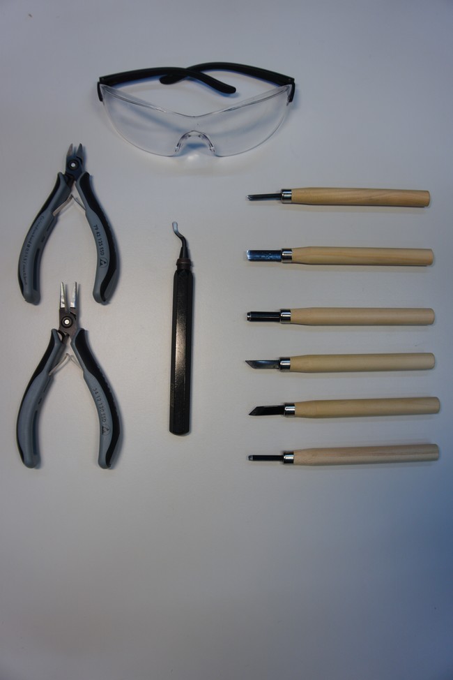
The following tools are optional but recommended as they make post processing much easier.
- Deburrer- To clean up the remains of the brim.
- Small Pliers - To remove the bulk of the support material.
- Wood Carving Set - To remove remains of support material.
All parts were printed with PLA, a 0.4 Nozzle, 0.15 mm layer height and 20% infill. These settings were a good compromise between speed and detail. Other settings can work but expect some experimentation regarding tolerances.
The parts were designed to require as little support material as possible (see waterdrop shaped holes in chassis). For certain parts it is therefore best to disable support material entirely as it adds a lot of unnecessary post processing work. Check out the Excel sheet located here that contains the recommended print settings for each part.
It is recommended to make a test print of the wheels, wheel brackets and their accompaning mounting plates before printing all six. The same goes for the bogie and the bogie bearings.
The brim and support material is removed after each print. It is recommended to first remove the majority of the brim with pliers or by hand and to afterwards clean up the edges with the deburring tool.
In case the parts warped, double check the part still fits together with the other parts it is interfacing with.
Bolts are used to mount most parts as they ensure a reliable and strong connection.
Direct Cutting Most holes were printed without threads with the intention of having the screw cut the thread on first insertion. This is sufficiently strong and cuts down on post processing, print complexity and the number of parts.
There are a few downsides to this technique however. The dimensions and thus the fit might differ depending on the printer, the settings and the material used. Thus some trial and error might be needed. In case a screw has to be removed and reinserted it is crucial that the previous thread is detected and reused. Otherwise, a second thread will be cut, which makes the connection weaker or even unusable. To find the previously cut thread rotate the screw counterclockwise until you feel and hear it click. Then simply tighten the screw.
Threaded Inserts A more advanced threading is used for parts which carry a high load and are inteded to be removed regularly. In ExoMy, this is the top cover which carries the solar panels and mast/head unit. There, threaded inserts were inserted into the chassis as the top is expected to be removed fairly often.
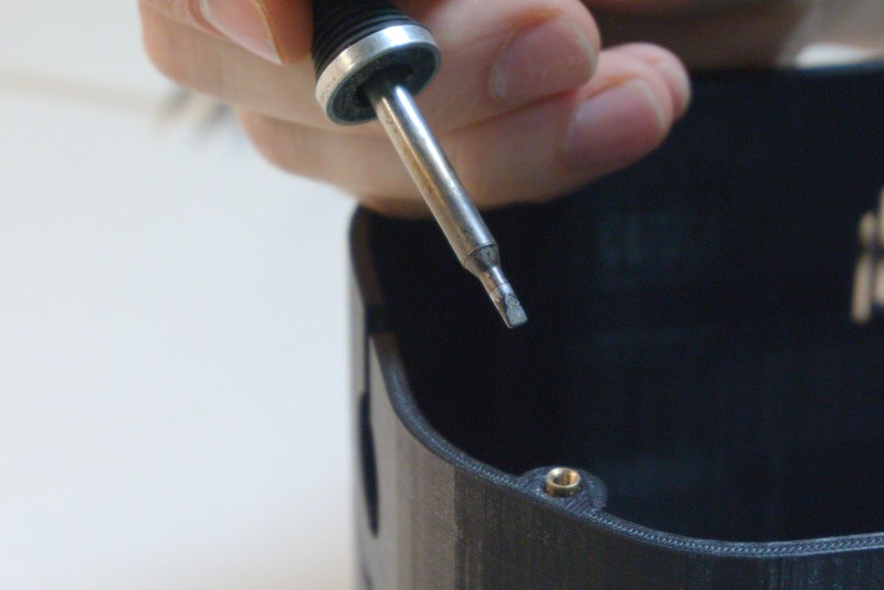
The easiest way to install the threaded inserts is to use a soldering iron. Place them on the tip and slowly insert them into the part as shown bellow and here
Practice on a test print before installing them into the body. It would be a shame to ruin such a large print.
Multi Color Printing
The solar panels were printed using the dual extruders of an Ultimaker 3. Use the P12_Solar_Panel_*_fill.STL and P12_Solar_Panel_*_shell.STL files and combine them in your slicer if you want to print the solar panels in multicolor as well. Here is an article on how to do it in CURA.
Single Color Printing
If you want to print the solar panels in a single color you can simply print the P12_Solar_Panel_*.STL files.
ExoMy's mouth and hat can easily be customized using either SolidWorks or the CAD software of your choice. The same procedures apply for the mouth. Simply replace P26_Hat with P25_Mouth.
With SolidWorks
Open P26_Hat.SLDPRT. In the Configurations tab you will see all the hats designed by us. Double click the Default configuration. You should see a default file without any customization. Add a new configuration and make sure it is active. Finally you can go to town and let your creativity run wild to design a new hat for ExoMy.
With Other CAD Software
Import the P26_Hat_Default.STEP file into your CAD software and start designing your hat!
Necessary Tools
- Soldering iron and lead
- Pliers
- Multimeter
Optional Tools
- Helping hands
- Insulation stripping tool


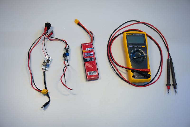
The output voltage of the DC/DC converters can be adjested using the blue potentiometer. It is important to carefully set the correct voltage in order not to damage the Raspberry Pi or the motors. You will need the wire harness, that you finished in the previous step, the LIPO, a thin flathead screwdriver and a multimeter (preferably with some clamps).
Turn off the power and motor switch and connect the LIPO to the wire harness.
Identify the DC/DC converter connected to the USB cable. This will power the Raspberry Pi and should be set to 5V.
Activate the main switch and measure now the voltage between the two output terminals on Raspi DC/DC converter. It helps to use a friend or some multimeter clamps to hold a steady connection to the terminals while you adjust the potentiometer.
/images/manufacturing_instructions/electronics/02_dc_dc_calibration/DSC05639.jpg
Check in the motor datasheet, what the maximum rated voltage of the motors is. Our motors are rate to 6V, so the motor's DC/DC is set to 6V in the same way as the Raspi DC/DC converter.
For a cleaner asthetic and 100 style points, it is recommended to route the cable of the steering motors inside of the casing instead of externally.
This step isn't required, but neither is bathing. Think about it.
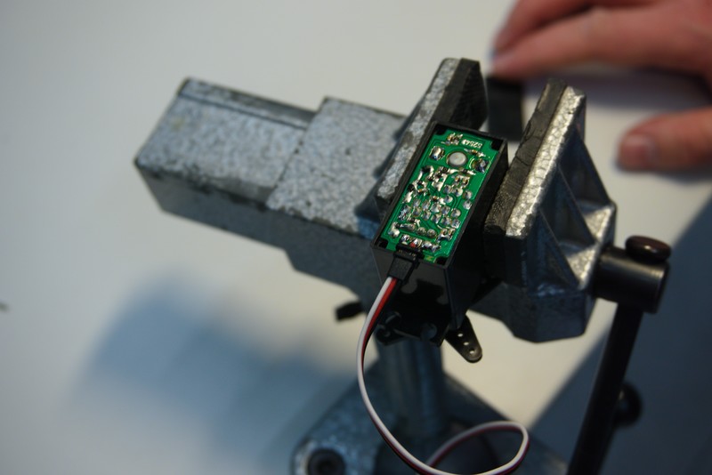
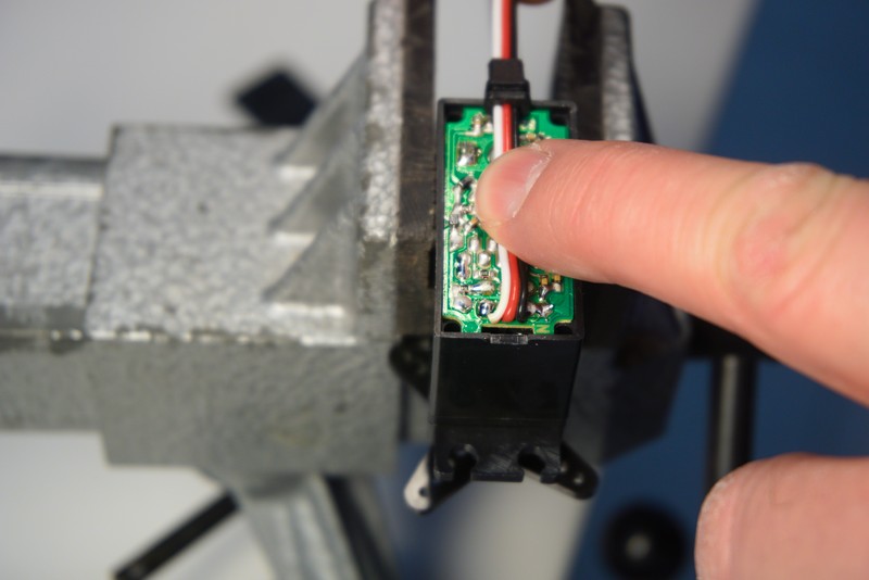
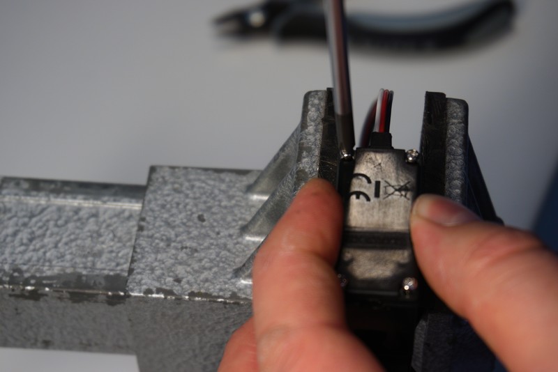
Begin by fixing the motor in a vise and removing the screws.

Remove the cap to reveal the PCB.
Next, carefully cut a slit into the black plastic seal using pliers. It will be move to the other side of the casing after rerouting the cable.

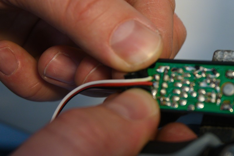
The cable will afterwards run accross the PCB. The Pins from the components would spike it and create a short.
It is thus very important to cut the pins as short as possible. Use your pliers to carefully cut the pin in the center, where the cable will be laying.
Do not cut multiple pins at the time as you could rip out traces from the circuit board by doing so.
The cut off pins will fly away! Wear safety glasses!

Route the cable accross the freshly cut path and reattach the previously cut cable seal.
Now, reinstall the cap. Make sure reorient it so the cutout in the cap is on the side of the seal! Otherwise, your cable will not fit.
- Raspberry pi will not display via HDMI if it is not connected to it before boot.