Hardware
The hardware is based on a Atmel AVR microcontroller and the V-USB library. No special SMD parts are needed to build the device, just some standard parts and DIL chips. The price for the PCB board and the parts are around 10 EUR. It is possible to build the device on a perfboard or on a plugboard, but a professional premade PCB board is easier to handle (and carry around).
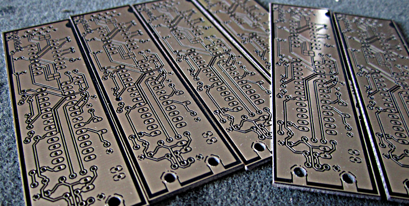
The board layout is designed to use as little space as needed (35x100mm) to place all components on it and get six boards out of a single 100x160mm EURO PCB board. This makes it possible to use a professional PCB etching service like Platinenbelichter or a other service. The Eagle layout is in the /pcb directory and can be directly send to an PCB service.

The following list includes all the parts (in German) which are needed to build the device. It is advisable to use the small version of the part for better placement on the board, especially the capacitors. A preset shopping card for Reichelt can be found here.
| Parts | Reichelt Article Nr | Name | Amount |
|---|---|---|---|
| D1,D2 | ZD 3,6 | Zener Diode 1,3W 3,6V | 2 |
| X3 | D-SUB BU 09EU | D-SUB-Jack, 9 pin, angled, RM 9,4 | 1 |
| R7,R8,R9 | 1/4W 220 | Carbon film resistor 1/4W, 5%, 220 Ohm | 3 |
| R4,R5 | 1/4W 68 | Carbon film resistor 1/4W, 5%, 68 Ohm | 2 |
| R1 | 1/4W 22K | Carbon film resistor 1/4W, 5%, 22 K-Ohm | 1 |
| R2,R3,R6 | 1/4W 1,5K | Carbon film resistor 1/4W, 5%, 1,5 K-Ohm | 3 |
| Q1 | 20,0000-HC49U-S | Quartz, 20,0 MHz | 1 |
| C8,C9 | KERKO 27P | Ceramic capacitor 27P | 2 |
| C1,C7,C10 | KERKO 100N | Ceramic capacitor 100N | 3 |
| C2,C3,C4,C5,C6 | SM 1,0/63RAD | Electrolytic capacitor, radial, 1,0µF/63Volt | 5 |
| ACTION | LED 3MM 2MA GE | LED 3mm, low-Current, gelb | 1 |
| WRITING | LED 3MM 2MA RT | LED 3mm, low-Current, rot | 1 |
| POWER | LED 3MM 2MA GN | LED 3mm, low-Current, grün | 1 |
| X1 | USB AWF | USB-jack, A series, angled, slim edition | 1 |
| GS 28-S | IC-Socket, 28 pin, doubled spring contact | 1 | |
| GS 16 | IC-Socket, 16 pin, doubled spring contact | 1 | |
| IC1 | MAX 232 CPE | RS232-Driver, DIL-16 | 1 |
| IC2 | - | ATMEGA328P-PU | 1 |
The ATMEL microcontroller ATMEGA328P-PU cannot be buy on Reichelt. You have to buy it somewhere else (like ebay or in your local electronic shop).
If the board is professionally etched, you can go right away and solder all parts on the board according the image and the table above. Keep an eye on the polarity for the C2,C3,C4,C5 and C6 capacitors, the zener diodes D1 and D2 and the LEDs. If you are unsure in what direction the part should fit in, have a look in the schematics file (found in the /pcb directory).

-
Check all soldering. If you are unsure, take a multimeter and check the wires. Some strange things can happen, if one single wire is not correctly soldered. If you have to much solder on a pad, use a wentletrap or heat the solder and gently tab the board to remove it. If a conducting path on the PCB is detached from the surface, remove it completely and use a wire to build a clean and solid connection.
-
Check the parts. Some parts (especially LEDs and ICs) gets damaged if they getting to hot to long. Don't put the soldering iron to long on the pads to save the part and the pad itself. You can check most of the parts with a multimeter if it operates properly.
-
Check the connections and plugs. Is the USB jack correctly plugged into a USB port on the PC? Are all pins inside the USB jack intact? Is the RS232 connector correctly connected and are all pins intact? What about the power supply? Are the microcontroller gets its 5 Volts from the USB jack?